1-Introduction
"This theory is too artificially to be true!". This remark was made more than a century ago by the famous German metallurgist A.Ledebur [1] when Osmond suggested that there might exist more than one allotropic modification of iron. It lasted ten years before this idea broke through. This is only one example that shows how easily new and unorthodox ideas are waved away, almost swifter than they can be put on paper. This study risks the same fate, as many of the statements made herein are completely different from traditional and general accepted opinions.
2-The development of theories on graphite formation in cast iron.
Cast iron is one of the oldest cast alloys in history and certainly the only one that had two lives: the one before the invention of nodular iron and the one after that. It is also regarded as the most complex alloy, caused by its wide range of composition and the variety of structures that can be obtained. The most typical structural component and at the same time the most influencing one, has always been the graphite phase. It's not surprising therefore, that in virtual every study on gray or ductile cast iron, attention has been focussed on graphite formation. Many ideas and theories were proposed during the last century in order to explain the mechanism of graphite formation in the various types of cast iron. The chronological development of theories on spheroidal graphite are described in detail by the author elsewhere [2,3] and also published on the Internet. As can be followed from the surveys, many theories have appeared, were adapted, combined, abandoned, forgotten or replaced by others.
-2.1 Present day's views.
From the sixties on, graphite in cast iron is generally regarded as a eutectic phase that directly forms in the melt, whilst some older theories based on decomposition of previous formed carbides or carbon deposits from supersaturated austenite are abandoned since. Today's views on the solidification of ductile cast iron can be summarized as follows:
-Primary austenite is deposited until the remaining liquid becomes eutectic.
-Carbon crystallizes as graphite on certain nuclei that are present in the melt.
-Formation of graphite is independent of any other component.
-The typical spherical shape is caused by a chemical or physical influence on the growth of the graphite crystals.
-Further growth of the nodule takes place either by deposits of carbon directly from the melt or by carbon diffusion through an solid austenite layer that surrounds the nodule, or by a combination of both.
-Eutectic austenite is deposited onto the primary austenite or around an existing nodule.
2.2-A critical note.
At first sight there seems to exist an acceptable agreement on the way nodular graphite is formed. However, when the existing theories are evaluated in more detail, it appears that many fundamental differences still exist. Disagreements can be found on the growth mode of nodules, the role and function of the eutectic and primary austenite, the composition and the role of nuclei and the microstructure of a nodule itself [2,3]. The ultimate differences in views are reflected in the various ways the graphite eutectic in ductile cast iron is supposed to form and are shown in fig.1 Figure 1A, Austenite-shell theory, originally proposed by Scheil[4], and although highly questioned since [5,6], still popular today [7].
Figure 1B, Austenite-shell theory with additional introduction of primary and eutectic austenite dendrites [8,9]
Figure 1C, Dendrite encapsulation theory, the function of the austenite shell is fully taken over by austenite dendrites [10].
3-A different approach.
If there can exist so many differences within a commonly accepted theory, one is inclined to believe that this is so, because:
-All proposed mechanisms can take place, depending on circumstances, or
-Some additional mechanisms are still unknown, but will eventually be found
These relatively reassuring views seem to be confirmed by the huge amount of research work that is done in this field as well as the controlled properties of ductile cast iron that can be achieved in practice. Another reason for the existence of the variety of ideas, however, might be the rather uneasy thought that, in trying to explain graphite formation in cast iron:
- we are used to choose a fundamentally wrong starting point!
If one considers the theories that are popular at present and take out all existing differences, then the remaining general agreements are in fact limited to the following basic starting points:
*Graphite formation dictates the solidification of ductile cast iron
*The formation of the iron phase is only of secondary interest
*The validity of the Iron-carbon diagram is accepted.
It is clear, that the interpretation of observed facts will be strongly influenced by the above mentioned starting points. As already so much research work has been done, based on the above mentioned points -but not leading to a unified concept on graphite formation in cast iron-, would it not be worth while to take an alternative routing? Experience showed that it is extremely difficult to free oneself of existing opinions and ideas, which on themselves seem logical and moreover, are widely accepted in foundry industry and materials science. The author managed, however, to study the solidification of ductile cast iron in such a way that the interpretation of observations are least influenced by these basic starting points, simply by reversing them. This means that the solidification of ductile cast iron was studied with the following basic ideas:
*The formation of graphite is only of secondary interest
*The iron phase dictates the solidification of ductile cast iron
*The Iron-carbon diagram will not be used for explanation.
The third point might present a rather sensitive one, as the Fe-C and related diagrams form the established base of cast iron metallurgy. However, as attempts to apply the presently known Fe-C and Fe-C-Si diagrams to the analysis of solidification of cast irons are quite unsatisfactory [11], and many discrepancies exist, equilibrium diagrams should not be used in an early stage in the explanation of certain solidification phenomena.
4-An alternative look at the graphite phase.
Graphite in cast iron is such an obvious and dominating phase, that it is difficult to look at it otherwise. The amount, distribution and shape of the graphite phase has always been regarded as the governing factor in cast iron solidification. Since the general acceptance of the melt theory and the introduction of the nodular shape, attention was focussed even more on the graphite phase. In order to explain the various shapes in which graphite occurred, branching and crystal growth mechanisms were added to the nucleation theories that already existed. The special attention that was given to the nodular graphite shape and since then remained, can best be illustrated by the following quotation from the first publication on nodular structures [12]: "To the author's knowledge, the occurrence of the spherulitic structure in cast irons and in the alloys described in this paper is unique in the whole field of metallography, and may perhaps be attributed to the unique crystal structure of graphite". Various publications, however, can be found in which ball-shaped forms of non-graphitic inclusions occur, even long before the former remark was made. As far back as 1936, for instance, some interesting nickel-microstructures were shown [13]. The shape of the nickelsulfide inclusions depends on small additions made to the melt. Addition of manganese, changes the grain boundary-shape to flakes, magnesium into a nodular form. Normally one would not speak of a typical crystal growth mechanism to explain these changes in shape, but rather regard the sulfide separations simply as segregations, where the shape is determined by the solidifying nickel crystals. To explain the occurrence of graphite in cast iron of practically the same shapes, however, we are used to consider the influence of complicated nucleation and crystal growth mechanisms.
The shape of sulfide inclusions in cast iron are reported to change from elongated to spherical, depending on the melt treatment [14]. No particular mysterious crystal growth mechanism was indicated as the cause for this change.
The shape of gas inclusions in aluminum alloys [15], can change from compacted to spherical, depending on metal treatment and can certainly not be dictated to a crystal growth mechanism.
Another interesting example is shown in photographs 1 to 4. In a mains frequency electrical furnace, by mistake, a cast iron charge was made up, containing 10-15 % of aluminum bronze.
Photo 1 shows the structure of a sample of this material, taken during tapping at low temperature. Suspended copper inclusions, with dimensions up to 3 mm. can be found, many of them in a spherulitic shape.
If one studies these inclusions more accurate, however, many can be found that are not spherical at all, but show protrusions that follow the solidification front of the iron phase as photo 2 indicates.
Photo 3 shows the solidification front between cast iron and a copper inclusion. Many dendritic iron protrusions, reaching far into the copper inclusion can be seen. The shape of the copper 'nodule' was apparently forced upon by the solidifying iron phase.
In the same sample, but at higher magnifications, elongated copper and graphite 'flakes' can be found intermixed (photo 4).Both types of separations point to grain boundary segregations, rather than to entities that crystallize and grow directly in this shape from the melt.
Many reasons for the formation of the spheroidal graphite shape have been given: surface tension, interfacial energy, crystal growth defects, preformed shape by small gas bubbles etc. The above mentioned examples, however, clearly show that in order to obtain a spherical inclusion, it is not absolutely necessary to assume a typical growth mechanism or a preformed bubble-shape, but that it can also be produced under the influence of the solidifying surrounding matrix. Non-perfect nodules offer the best way to examine the influence of the solidified matrix on the graphite shape. If in the photos 5, 6 and 7 the graphite is ignored and concentration is kept on the matrix, the dendritic protrusions on the circumference can clearly be identified, supporting the above mentioned mechanism.
These photographs show that the final graphite shape might be the result of its surroundings and not the result of an intelligent and complicated growth mechanism of the graphite itself!
5-Influence of the primary matrix structure on the graphite phase.
The presently known facts of the influence of the primary austenite structure on graphite formation are rather limited. An extensive literature survey on the primary solidification of gray iron by the author [17], showed that all process variables that influence graphite formation, also influence the primary structure.
Primary structure played an important role in the majority of earlier theories on the formation of nodular graphite. This role was minimized with the introduction of the melt theory, but the primary phase seems to be regaining interest during the last decade [10,18]. Primary structure only seems to draw attention as long as it can readily be distinguished; if this is not the case, its existence is almost ignored. In view of the above mentioned facts, revealing the primary structure might turn out to be a major factor in the understanding of graphite formation in ductile cast iron.
6.0 Revealing the matrix structure.
Usually, the matrix structure is only revealed by etching. The most popular etchants that are used in the examination of ductile cast iron, are diluted solutions of picric or nitric acid in water or alcohol e.g Nital and Picral. Structures revealed by these etchants have served as a basis for the development of theories on graphite formation.
However, these etchants reveal only minimal information on the primary structure, i.e. the structure as it existed just after solidification.
6.1-Oxidizing etching treatments.
Another, much less known group of etchants, form the oxidizing or color etching treatments. These methods are particularly suited to revealing the primary structure of cast iron. Instead of attacking by means of chemicals, oxidizing etchants work by releasing a tiny layer of oxides to the surface of the specimen. The thickness of this layer depends largely upon the chemical composition of the underlying surface and the etching conditions. Although various compositions are in use, the best results were obtained with the etchant according to Becker [20]. Detailed information on color etching can be found in
Color etching
7.0 The Primary Structure made visible.
Microstructures always formed a major contribution to the development op solidification theories. The view as it is seen under the microscope can have a decisive influence on these theories, most certainly in the case of ductile iron. This is best illustrated in photo 8, which represents the structure of a ferritic Ductile Iron after a nital etch, showing graphite nodules (nodule count 350 nodules/mm2), ferrite grains and some pearlitic islands. Photo 9 represents the same specimen, but primary etched. This reveals a completely different image, showing more or less coherent regions within the matrix, each containing one or more nodules. The same type of coherent regions can be found in other matrix structures. They even remain visible after heat treatment. The structures revealed, although rounded and somewhat malformed, undoubtedly represent a dendritical pattern in the matrix, as is even better illustrated by photo 10. Little imagination is needed to predict that theories on nodule formation could have been different, if right from the start, use had been made of these primary etchants.
Photo 8------------------Photo 9------------------Photo 10-----(Magnification 50x)
7.1 Primary structures in real castings.
Identical structures are reported to be found in castings, irrespective of whether the solidification time lasts one minute or many hours [21]. This is confirmed by photo 11, that represents the structure of a 400 mm. diameter. massive cylinder. (Chemical composition: C% 3.5 , Si% 2.3 , Mn% .15 , P% .03, Mg .05 ).This photograph shows the increase in dimension of dendrites with increasing wall thickness. It is also evident, that it is impossible to obtain an overall view of the full relationship between the different parts of the dendritic regions, by using a normal microscope. If this is disregarded, a wrong conclusion can be drawn that a dendritic structure does not occur in thick walled castings [22]. Photo 11 Piece L=120mm, taken from a section through a 400 mm. wide cylinder. Casting wall to the right.
7.2 Three dimensional dendrites.
Dendrites in ductile cast iron shown so far, are exposed in two dimensions. In reality, however, dendrites form three-dimensional objects and should be studied as such.
Obtaining real dendrites in this shape is not easy. However, the production of a large number of heavy castings (3000 to 6000 kg. casting weight), offered an excellent opportunity to collect three-dimensional dendrites. Dendrites on the downsprues (diam.120-140 mm.) could be found when the pouring basin was removed at a time that solidification was almost complete. The solidification front as it exists at that very moment, is torn apart and becomes fixed by rapid cooling on exposure to the air as is shown by photo 12.
Photo 12. A fracture of a 120 mm. down-sprue, covered with small dendrites
Photo 13. Macro photograph of the same fracture.
7.3 Microscopical examination of the dendrite structure.
Several individual dendrites and agglomerates of dendrites up to 15 mm in length could be isolated as shown by photo 14. Photo 14, Isolated dendrites.
In order to study a dendrite, it was placed within a metal ring fitted with some fixing bolts, and cold curing resin poured into the ring until the dendrite was partially embedded. The construction of the specimen is shown in fig.2.
In this way it was possible to examine the dendrite on a microscopic and macroscopic scale at the same time.
Photo 15 represents a section through such a prepared dendrite, etched with nital. The structure is fully ferritic, nodules of various sizes can be seen. The nodule count was about 150 nodules/mm2. Essentially, however, this can be considered to be a structure that is usually found in this material.
Photo 16. The same section, but primary etched. The image here is quite different. A dendritic structure, which fails completely in the nital etch, is clearly visible now.
8.- Position of graphite nodules within a dendrite.
8.1 Planar position
Nodules can be found, partially within the dendrite, partially on the outside of the dendrite arms. The position of the nodules with respect to the dendrite stems, is in agreement with earlier observations [23,24].
8.2 Spatial distribution
By making a large number of successive grindings (serial sectioning), good insight could be gained as to the spatial structure of a dendrite and the nodules that lie within it. Photos 17-20 show the structures obtained after successive grindings, polishing and etching of the same specimen. Layers of 10 to 50 mu thickness were taken off in each grinding.
Photos 17-20 (Magnification: 50x)
This series of microphotographs indicates that dendrites show a layer wise construction. The photos reveal that a dendrite, when in a vertical direction, comprises a layer with clearly visible dendrite arms, followed by a layer containing rings of ferrite, at first sight without mutual connection. In the first layer, nodules can be found at the perimeter of the dendrite arms. In the second layer, nodules are confined to the ferritic shells. The third layer again shows a dendritic structure, followed by a layer consisting of ferritic shells containing nodules etc. Such order can be found throughout the whole dendrite. Note that within a single dendrite the same basic structures are found that form the main controversial versions of the melt-theory, as mentioned in 2.2. A common relationship, rather than controversy may now be expected.
8.3 The solidification of primary and eutectic austenite
It is important to note that, although dendrite arms appear to be more or less massive in the photographs, it can be assumed that all arms and branches are composed of numerous tiny branches in a fractal-like construction. They can be revealed in limited detail after annealing as is shown in photo 21.
Photo 21, dendrite arms are built up from tiny branches.
It should be noted that the etching colors shown are not absolute. By using prolonged etching times, dendrite arms finally occupy the whole surface, but even then, the basic dendritic structure still remains distinguishable as shown by photo 22. Photo 22.
8.4 The number of nodules within a dendrite
As it is shown that all nodules are found within a dendritic structure, it is interesting to examine the number of nodules that lie within one single dendrite. A number of isolated dendrites and conglomerates of dendrites were weighed, the number of visible dendrites counted and the average weight calculated, which was in this series 1.2 grams per dendrite. Using a specific gravity of 7 gms/cm3, meant an average volume of 170 mm3.
The nodule count was 150. Using Noguchi's formula [25,26], it is possible to calculate the spatial nodule count:
Nodules/mm3= 10.6 * (nodules/mm2) 1.35 Nodules/mm3= 10.6* 150 1.35 = 9184
One single dendrite took a volume of 170 mm3. Therefore, in a single dendrite 170 * 9184= 1.500.000 nodules occur.
According to existing theories, the formation of every nodule starts on a nucleus. For the above mentioned example, it would mean that in order to construct the 1 gram dendrite, and to account for all the graphite nodules in this single dendrite, we need: 1.5 million nuclei, at the right time, the right place and of suitable composition. Such a mechanism is virtually impossible.
Dendritic growth, with its multiplying branching, however, can easily produce this number of sites for graphite formation.
8.5 Sites for nodule formation
Indications were found, that during their growth, austenite arms branch and grow together, enclosing certain liquid regions from the remaining melt, as is illustrated in photos 23 - 26.
As during graphite formation, a increase of 4 times of its original volume occurs, the enclosing dendrite arms are deformed and bend outwards. Calculations on the possibility of plastic deformation of the austenite walls were made long ago [27].
9.-The formation of spherulitic graphite.
Up to this point, this study offers a logical and uncomplicated explanation for the huge number of sites for graphite formation as well as for the distribution of these sites within the matrix. It does not tell why graphite separates at these sites. Not one rule in metallurgy demands that solidification takes place exactly at the magnitude as it can be seen in the microscope. Nevertheless, graphite inclusions have long been regarded as a single and massive component its final macro shape (flake, rosette, nodule, undercooled, compact etc) being caused by some special growth mechanism of the graphite itself. The fact that graphite in cast iron is not a single crystal, but a polycrystalline component is often ignored in the explanation of the growth mechanisms. Various publications [28-30], especially recent Chinese research work [31-33], clearly show that all graphite inclusions in cast iron are composed of tiny flakelets. Following traditional ideas, these flakelets are assumed to be produced by the growing graphite itself. Hardly ever mentioned, however, is the fact that the iron phase is also polycrystalline, i.e., is composed of many crystals (or dendrite branches). So, why would not every single iron crystal produce its own equivalent graphite particle? As the austenite crystals continue their growth, the graphite particles that form directly in front of it, can be displaced by the pressure exerted on them [34]. At the end of solidification, graphite particles are agglomerated and compacted by the austenite crystals, thus forming a polycrystalline graphite inclusion. This ramification action is supported by the fact that the core of a nodule is less dense than the outer region [35].The final shape of the inclusion thus depends on the way austenite dendrites grow and close in on the graphite particles. Further graphitization of the compacted graphite flakelets may take place on cooling, influenced by pressure and temperature.
During the course of this research, a completely new idea about graphite formation in cast iron evolved, which for the very first time could bridge the gap between the various graphite formation mechanisms. In this view, graphite separation is no longer regarded as the result of a eutectic reaction, but the result of a catalytic reaction on a suitable austenite substrate. Details are given in "A Proposal for a general and unique mechanism for graphite formation in all Iron-Carbon Alloys"
9.2 Factors that influence austenite dendrite growth.
Mainly because the austenite phase has been neglected in the past, little is known on the factors that influence their growth. A direction can be given, however. The influence of processing variables on the primary structure of cast iron as was mentioned earlier, probably also holds for ductile cast iron. Recent research on cast steel, showed that the primary structure changed completely from dendritic to globular after the addition of only 10 % of the amount of magnesium that is normally used in the production of ductile cast iron [36]. Earlier research on cast steel [37], showed that the primary structure is influenced if during austenite crystallization, simultaneous separation of impurities take place. These impurities involve oxides, sulfides as well as their eutectic mixtures. Note that these are the same compounds that are regarded as 'nuclei' to act as substrates for graphite formation in cast iron. Varying dendrite growth can explain many of the abnormal graphite shapes that can occur in ductile cast iron.
9.3 Variation in nodule size.
The fact that nodules of different size occur, depends in this concept upon the degree of growth that is allowed for the dendrite arms before they are hindered by neighboring crystals and thus throw off new, but smaller arms. The largest pools will be found closest to those branches which were the first to form as is illustrated in photo 16, where large nodules ly exclusively in the largest arms, closest to the main stem.
9.4-Duo-nodules.
The formation of duo-nodules was discussed in literature as a peculiarity and was even used as evidence for the formation of graphite directly from the liquid [38,39].
However, dendritic growth of the austenite phase easily explains the formation of duo- and even trio-nodules, as their formation depends solely upon the manner in which neighboring dendrite branches are able to complete their growth.
9.5 Variations in nodule shape.
Following established theories, it is believed that a deviation in shape is caused by a change in crystal growth under the influence of disturbing elements, differences in nucleation, or the presence of channels in the austenite shell. Paragraph 4 showed, however, that it is equally well possible to obtain various shapes by the interaction of two individual constituents. If the liquid regions that are enclosed by the growing austenite dendrite are more or less regular, a ball-shape will result. If the region is irregular, the graphite shape will be influenced by the existing contours of the austenite solidification front, resulting in 'degenerated' shapes. If the region is not completely closed, the expansion occurring during the deposit of the carbon particles pushes some of the available carbon into these channels. Photos 25 and 26 show such deviated shapes.
10. Comparison of the proposed "Dendrite Growth" theory with the existing theories.
Figure 5 represents the various stages during the solidification of hypo eutectic nodular cast iron. In this figure, the "Dendrite Growth Theory" (A) as proposed by the author is compared with the two main variations of the melt-theory as indicated in fig.1 and named B, respectively C.
'Main' and' side' arms must be interpreted as being relative.
Stage 1: formation of 'main' stems and side arms.
This formation is exactly the same for all three theories.
Stage 2: further growth of 'side' arms.
This formation is also exactly the same for all three theories.
Stage 3: Enclosed melt reaches eutectic composition. Start of graphite formation.
A: Growth of the primary austenite continues. Small graphite flakelets are formed directly in front of the growing austenite branches.
B: Growth of the primary dendrite arms stops. A nucleus of specific composition must be available now at the right spot, where graphite can crystallize on. The equivalent amount of 'Eutectic' austenite settles on the existing primary dendrite arms, no distinction between the two can be made.
C: Growth of the primary dendrite arms stops. A nucleus of specific composition must be available now at the right spot, where graphite can crystallize on. The equivalent amount of 'Eutectic' austenite settles around the formed tiny nodule after a certain time.
Stage 4: Further 'eutectic' growth.
A: Growth of the primary austenite continues. More small graphite flakelets are formed directly in front of the growing austenite branches. By now, the liquid pool is closed. Any chemical compound that is already present in this liquid pool or will form at a later stage will be trapped and can be found afterwards.
B: The graphite nodule continues its ball-shaped growth by a crystal growth mechanism that is determined by chemical substances available. 'Eutectic' austenite still settling on the primary austenite. By now, the primary dendrite has 'eaten up' the nodule.
C: The graphite nodule, isolated from the melt by the austenite shell, grows because carbon from the melt diffuses in the shell, travels through it and deposits itself onto the existing nodule. At the same time, the 'eutectic' austenite settles onto the shell and make it increase in diameter.
Stage 5: Continuation of stage 5.
Stage 6: solidification completed
A: The growing primary austenite has used up all iron that was available within the liquid pocket. The equivalent graphite flakelets are compressed, forming the nodule. The circumference of the nodule is determined by the way the dendrites arms closed in on the graphite as well as the pressure caused by the volume expansion of the graphite.
B: The remaining iron phase in the pocket has settled on the primary austenite.The last stage of nodule growth is supposed to occur by diffusion of carbon from the main liquid to the graphite nodules through the enveloping austenite.
C: Growth of the nodule and the accompanying austenite shell continues until all liquid is used up. Primary austenite and 'eutectic' shell 'melt' together in such a way that both phases cannot be distinguished anymore (not indicated in figure).
10.1 Discussion on the results of this comparison.
As is indicated in stages 1 and 2, the first part of solidification stays in all three theories the same. From stage 3 on, B and C need extra mechanisms for the continuation of solidification. Both need specific nuclei for graphite formation and an additional mechanism to tell the 'eutectic' austenite where to go to. In stage 4, theory C needs again another double mechanism, diffusion of carbon through the surrounding austenite and deposition on the existing nodule. Theory B supposes this same mechanism in stage 6. None of these (hypothetical) extras are required by theory A. The main difference with existing theories in fact being the proposal that a nodule is build up from tiny flakelets of which the final shape is determined by the surrounding austenite branches.
11. Hyper-eutectic ductile cast iron.
Cast iron compositions used so far were all slightly hypoeutectic. Strictly speaking, the proposed dendrite growth theory only applies to these compositions. Experience showed, however, that in virtual every discussion on this new theory, the attention is soon focussed on the hypereutectic region.
11.1 Existing views on graphite formation in the hypereutectic region.
For more than a century, the formation of Kish graphite in hypereutectic flake iron is known and used as a visible proof that graphite forms directly in the melt. According to the existing Iron-Carbon diagram, in hypereutectic compositions, carbon should be the first phase to crystallize, and because of the difference in specific gravity, graphite flakes tend to float to the surface and pop into the air. This view was taken over when graphite could be transformed in the spheroidal shape.
Although theories on Kish formation were completely overthrown twenty years ago [40,41,42], when it was established that Kish formation is a surface phenomenon and not the result of flotation of graphite particles, these new findings did not evoke any new view as to the formation mechanism of graphite in ductile cast iron.
All microstructures of floated graphite that are shown in literature so far, were unetched or nital etched. When a color etchant is used, however, a completely different picture is formed, as was the case for hypoeutectic material. Photo 27 clearly shows a hypereutectic graphite nodule encased within an austenite dendrite. Photo 28 indicates that parts of an exploded primary graphite nodule are forced into this shape by compact dendrite arms. It should be noted that in hypereutectic gray iron, primary graphite is also often surrounded by austenite structures (transformed into ferrite).
12-Concluding remarks.
With the proposed "Dendrite Growth Theory", the majority of phenomena that occur during the solidification of ductile cast iron can be explained in a way that is at least twenty times simpler and more logical than any other theory that has been proposed in the past fifty years was able to. If all provisionally findings, are taken into account, it means that the present views on the solidification of not only ductile iron, but also the other types of cast iron as well as the concept of the iron-carbon diagram must be fully revised.
As this research points to the fact that the austenite structure appears to be the governing factor in cast iron solidification, (and it was especially this structure that has been vastly neglected in the past), controlling this structural component, might allow the production of cast iron alloys in the as cast condition with properties that are unattainable yet.
Maybe future developments will show that there existed another "third" live for cast iron.
References:
[1] A.Ledebur, Einige neuere Untersuchungen und Theorieen über die Formen des Kohlenstoffs im Eisen und Stahl, Stahl und Eisen, Vol.6 (1886), pp.373-86.
[2] C.A.v.d.Velde, The Solidification of Ductile Cast Iron-A New Approach, AFS Special Report, 1997
[3] C.A.v.d.Velde, De stolling van nodulair gietijzer, een nieuwe benadering, Gietwerk Perspectief, Vol.15 (1995), nr.2 pp.4-9, nr.3 pp15-21, nr.4 pp.6-12.
[4] E.Scheil, L.Hütter, Untersuchungen über die Kristallisation des Gusseisens mit Kugelgraphit. Archiv für das Eisenhüttenwesen, Vol. (1953), pp.237-46.
[5] W.A.Tiller, Fe-C and Fe-C-Si Alloys, Seminar Proceedings June 16-18, 1964, Detroit.
[6] I.Minkoff, How do cast irons solidify? A review of micromodelling using the computer, supporting experiments and basic theory, The Foundryman, Vol. (1993), pp.16-22.
[7] D.Venugopalan, K.Pilon, A model for describing the distribution of matrix phases in ductile iron microstructure, AFS Transaction, Vol.97 (1989), pp.565-70.
[8] J.Lacaze, G.Lesoult, Modelling the formation of microstructures: The example of spheroidal graphite cast iron.... 1994, pp. 5-34.
[9] S.Chang, D.Shangguan, D.M.Stefanescu, Modelling of the liquid/solid and the eutectoid phase transformations in spheroidal graphite cast iron. Metallurgical Transactions, Vol.23A (1992), pp.1333-46.
[10] G.L.Rivera, R.E.Boeri, J.A.Sikora, Revealing the solidification structure of nodular iron,Cast Metals, Vol.8 (1995), pp. 1-5
[11] R.W.Heine, The Fe-C-Si solidification diagram for cast irons, AFS Transactions, Vol.94 (1986), pp.391-402.
[12] H.Morrogh, Williams, Graphite formation in cast irons, JISI, Vol.155 (1947), pp.321-371. Quotation pp. 325-26
[13] G.Sachs, Praktische Metallkunde, Erster Teil, Berlin, Verlag von Julius Springer, 1933.
[14] W.J.Williams, The influence of low percentages of certain elements on the microstructure of pure Iron-carbon alloys and cast irons. Journal of the iron and steel institute 1950, pp. 407-22.
[15] X.-G. Chen, S.Engler, Jahresübersichten, Leichtmetall-Sand und-Kokillenguß,Giesserei, Vol.81 (1994), pp.813. Original published in: Cast Metals, Vol.6 (1993), pp.99-108.
[16] R.W.Heine, The FeC transformation Diagram Related to Solidification of Cast Irons,AFS Transactions, Vol.78 (1970), pp. 187-93.
[17] C.A.v.d.Velde, De primaire stolling van grijs gietijzer, Gietwerk Perspectief, Vol.17 (1997), pp.7-14.
[18] D.M.Stefanescu, D.K.Bandyopadhyay, On the solidification kinetics of spheroidal graphite cast iron, Conference Proceedings, Cast Iron IV 1990, Materials Research Society.
[19] Robert Wlodawer, Gelenkte Erstarrung von Gusseisen, p. 375. Giesserei-Verlag G.M.B.H., Düsseldorf, 1977.
[20] U.Becker, Haunsheim. Personal communication.
[21] J.M.Motz, D.B.Wolters, Über Erstarrungsgefüge und Eigenschaften in dickwandigen Gusstucken aus ferritischem Gusseisen mit Kugelgraphit-Teil 1: Mikroseigerungen. Giessereiforschung, Vol.40 (1988), pp 69-79.
[22] J.M.Motz, Begeleidende elementen in gietijzer. Gieterij-Perspectief, Vol. (1988), pp. 23-
[23] A.Wittmoser, Graphitbildung in Eisen-Kohlenstoff-Gusslegierungen. Giesserei, Vol.46 (1959), pp 177-187.
[24] S.Engler, R.Ellerbrock, Über die Bildung von Austenithüllen um Graphitkugeln während der Erstarrung von Eisen-Kohlenstoff-Silicium-Schmelzen. Giesserei-Forschung, Vol.29 (1977), pp 141-145.
[25] T.Noguchi, K.Nagaoka, Three-Dimensional Distribution of Graphite Nodules in Spheroïdal Graphite Cast Iron. AFS Transactions, Vol.93 (1985), pp. 115-122.
[26] R.W.Heine, Nodule count:the benchmark of ductile iron solidification, AFS Transactions, Vol. 101 (1993), pp.879-884.
[27] J.D.Schöbel, C.B.Alcock, Some Considerations of the Theory of the Growth of Graphite Nodules in Solidifying Cast Iron Alloys. Zeitschrift für Metallkunde, Vol. (1966), pp. 74-76.
[28] R.Mitsche, G.Haensel, K.Maurer, H.Schaffer, Elektronenmikroskopische und andere Untersuchungen an normalen und entarteten Kohlenstofformen in Kugelgraphitgusseisen.34 Intern. Foundry Congress Paris, 1967. Nr.12.
[29] H.Itofuji, Y.Kawano, S.Yamamoto, N.Inoyama, H.Yoshida, B.Chang. Comparison of substructure of compacted/vermicular graphite with other types of graphite. AFS Transactions, Vol.91 (1983), pp. 313-324.
[30] O.G.Epanchintsev, M.P.Shebatinov, Graphite structures as observed with a scanning microscope, Russian Castings Production,(1971), pp.386-89.
[31] Baihe Miao, Keming Fang, Weimin Bian, Guoxun Liu, On the microstructure of graphite spherulites in cast irons by TEM and HREM. Acta metall. mater, Vol.38 (1990), pp 2167-74.
[32] Baihe Miao, D.O.Northwood, Weimin Bian, Keming Fang, Minz Heng Fan, Structure and growth of platelets in graphite spherulites in cast iron, Journal of materials science, Vol.29 (1994),pp.255-261.
[33] Fang Keming, Wang Min, Yu Zongsen, Beitrag zur Graphitausbildung im Kern von dickwandigen Gußteilen aus Gußeisen mit Kugelgraphit. Giesserei, Vol.82 (1995), pp.597-600.
[34] O.G.Epanchintsev, Interaction between austenite crystals and graphite particles during iron solidification, Russian castings production, Vol. (19..), pp.
[35] J.Kasperek, J-C. Tellier, M.Ortiz, Aspects de la germination du graphite dans des fontes synthetiques elaborees sous vide. Fonderie-Fondeur d'aujourd'hui, Vol. (1991), pp.29-37.
[36] E.Hofmann, G.Wolf, Verbesserung der mechanischen Eigenschaften von Vergütungs-Stahlguß durch Einstellen einer definierten Primärstruktur, Giesserei, Vol.84 (1997), pp. 20-26.
[37] H.Wentrup, H.Schrader, Untersuchungen über die Primärkristallisation von unlegierten und legierten Stählen, Archiv für das Eisenhütenwesen, Vol.20 (1949), pp.165-78.
[38] E.Scheil , J.D. Schöbel, Über den Entstehungsort der Graphitkugeln im erstarrenden Gusseisen. Giesserei Techn. Wissensch. Beihefte, Vol.13 (1961), pp. 203-213.
[39] G.S.Cole, Solidification of Ductile Iron. AFS Transactions, Vol.80 (1972), pp. 335-348.
[40] E.V.Zakharchenko, E.P.Akimov, C.R.Loper Jr., Kish graphite in gray cast iron, AFS Transactions, Vol.87 (1979), pp.471-76.
[41] C.R.Loper Jr., E.V.Zakharchenko, Investigation of the development of kish graphite in hypereutectic gray irons, AFS Transactions, Vol.92 (1984), pp.281-87.
[42] S.Liu, C.R.Loper,Jr., Morphology of kish graphite, AFS Transactions, Vol.98 (1990), pp.385-94.
[43] H.Morrogh, Grauguss mit kugeliger Graphitausbildung. Die Neue Giesserei, Techn.-Wissensch. Beihefte, Vol. (1950), pp. 65-74.
[44] H.Kempers, Sphärolitenflotation bei Gusseisen mit Kugelgraphit, Giesserei, Vol. (1966), pp.841-46.
[45] E.N.Pan, K.Ogi, C.R.Loper,Jr. Analysis of the Solidification Process of Compacted/Vermicular Graphite Cast Iron. AFS Transactions, Vol.90 (1982), pp. 509-527.
[46] Exploded graphite in low C alloys A.K.Chakrabarti, J.M.Young, A study on low carbon grey irons, The Foundryman, 1989, pp.16-21.

 Figure 1A, Austenite-shell theory, originally proposed by Scheil[4], and although highly questioned since [5,6], still popular today [7].
  Figure 1B, Austenite-shell theory with additional introduction of primary and eutectic austenite dendrites [8,9]
  Figure 1C, Dendrite encapsulation theory, the function of the austenite shell is fully taken over by austenite dendrites [10].
  Photo 1 shows the structure of a sample of this material, taken during tapping at low temperature. Suspended copper inclusions, with dimensions up to 3 mm. can be found, many of them in a spherulitic shape.
 Photo 11 Piece L=120mm, taken from a section through a 400 mm. wide cylinder. Casting wall to the right.
 Photo 12. A fracture of a 120 mm. down-sprue, covered with small dendrites
 Photo 13. Macro photograph of the same fracture.
 Photo 14, Isolated dendrites.
 Photo 15 represents a section through such a prepared dendrite, etched with nital. The structure is fully ferritic, nodules of various sizes can be seen. The nodule count was about 150 nodules/mm2. Essentially, however, this can be considered to be a structure that is usually found in this material.
  Photo 16. The same section, but primary etched. The image here is quite different. A dendritic structure, which fails completely in the nital etch, is clearly visible now.
 Photo 21, dendrite arms are built up from tiny branches.
 Photo 22.
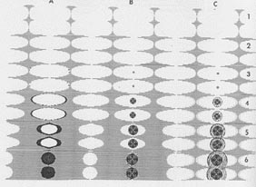
 Photo 27 clearly shows a hypereutectic graphite nodule encased within an austenite dendrite.
 Photo 28 indicates that parts of an exploded primary graphite nodule are forced into this shape by compact dendrite arms.